
Choosing a tubular chain conveyor vs pneumatic conveyor starts with a practical question: how must the material arrive at the next process? A transfer system must meet the required delivery rate without unacceptable changes in particle size, blend composition, cleanliness or operating reliability. A compact installation that cannot meet those conditions is not a successful selection.
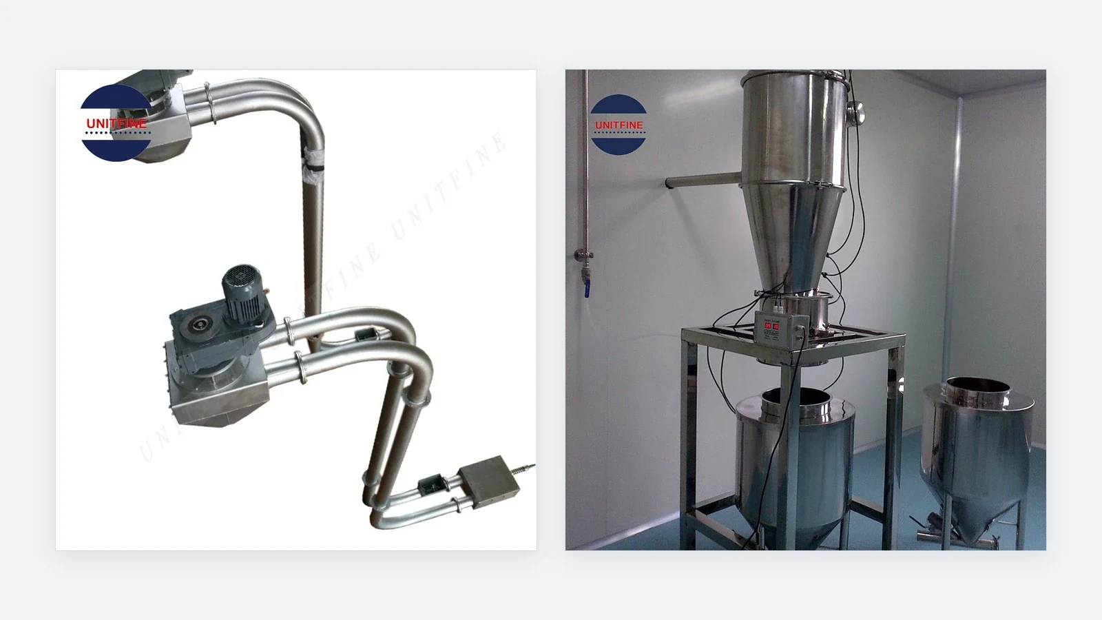
Quick answer: A tubular chain conveyor moves bulk solids mechanically through tubing using a chain-and-flight assembly. Pneumatic conveying moves solids with a gas stream driven by a pressure difference; vacuum conveying is one pneumatic arrangement. Compare both against the same material, route, duty and acceptance criteria. Neither is universally gentler, cleaner or cheaper.
What Is the Difference Between Tubular Chain and Pneumatic Conveying?
Tubular chain conveyor: a mechanical conveying circuit
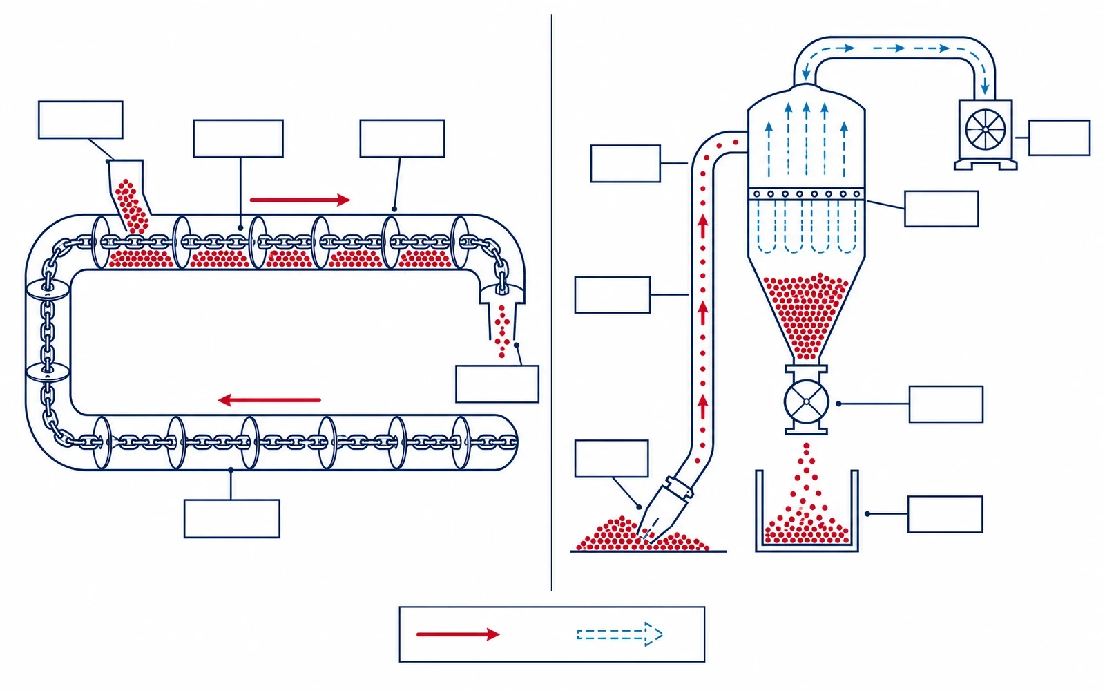
A tubular drag chain conveyor uses a moving chain fitted with flights or discs inside an enclosed tube. A drive pulls the assembly around a defined circuit; material enters at an inlet and leaves at the designated discharge points. The system includes a return path as well as the loaded conveying path. See the UNITFINE Drag Tube Chain Conveyor for equipment reference.
A tubular cable drag conveyor uses a cable rather than a chain. The two should not be treated as identical when assessing wear parts, tensioning or suitability. This article compares the chain-based arrangement with pneumatic transfer; cable equipment requires its own configuration review.
Pneumatic conveyor: gas-driven transfer
Pneumatic conveying uses a pressure difference to move material through a pipeline with air or another specified gas. A vacuum system draws material toward a receiver; a positive-pressure system pushes it away from a pressure source. Gas and solids must be separated at the receiving end.
Dilute-phase conveying carries relatively dispersed solids in the gas stream. Dense-phase conveying transports material at a higher solids concentration and can operate at lower material velocities in suitable applications. Vacuum versus positive-pressure operation and dilute versus dense phase are different classifications. Vacuum conveying is not necessarily dilute phase, and dense-phase conveying is not limited to positive-pressure systems. The conveying regime must be confirmed for the material and proposed equipment.
The UNITFINE UFLOW Vacuum Conveyor is the relevant vacuum-feeding product reference. Its published operating sequence includes suction, separation and discharge. Do not assume that a receiver delivering material in cycles provides a constant downstream flow without suitable integration.
Tubular Chain Conveyor vs Pneumatic Conveyor: Selection Table
| Decision factor | Tubular chain conveyor | Pneumatic conveyor | What to verify |
|---|---|---|---|
| Transfer mechanism | Chain and flights move solids through tubing. | Gas flow transports solids to a receiver. | Identify the actual equipment configuration, not just its trade name. |
| Product quality | Assess contact with flights, tube walls, inlets and discharge components. | Assess pickup, conveying phase, bends, receiver entry and discharge. | Measure fines, damage and blend variation before and after a representative trial. |
| Route and space | Allow for the conveying circuit, return path, drive and maintenance access. | Allow for piping, receiver, filters, vacuum source or blower and service access. | Review a dimensioned layout including lift, bends and available headroom. |
| Cleaning | Review access to chain, flights, tube interiors and retained material. | Review pickup, pipeline, receiver, filter and discharge-valve cleaning. | Define the residue limit and a documented changeover procedure. |
| Utilities and cost | Include the drive and all associated auxiliaries. | Include the gas mover and compressed-air services where used. | Compare complete-system energy per delivered tonne under the same duty. |
| Feeding behavior | Confirm inlet control, unloading and restart conditions. | Confirm pickup stability, receiver cycling and downstream buffering. | Check average output and short-term delivery requirements separately. |
| Maintenance | Inspect chain, flights, sprockets, tensioning and seals as applicable. | Inspect filters, seals, valves, bends and the gas-moving equipment as applicable. | Request a task list, parts list and access drawing for the quoted system. |
This table is a comparison framework, not a performance rating. It does not establish a maximum capacity, guaranteed energy saving, hygiene certification or material-compatibility approval for either technology.
Start with the Material and the Acceptance Criteria
Fragile granules and blended products
If breakage matters, define what counts as damage before requesting a test. A photograph of apparently intact particles is not enough. Agree a sampling method and compare particle-size distribution, fines generation or another relevant product-quality measure at the inlet and outlet.
For a blend, take samples throughout discharge rather than only at the beginning. Ask whether the delivered composition remains within the required tolerance across the batch. Compare both technologies using the same formulation, representative moisture and intended route. A successful trial with one ingredient should not be presented as validation of every future recipe.
Cohesive, abrasive or moisture-sensitive materials
Provide more than a material name. Include representative samples, bulk density, particle-size range, moisture condition and observed handling problems. Identify whether the material cakes during storage, forms lumps after compression or changes behavior with humidity. Record these observations as selection inputs rather than assuming that an enclosed conveyor solves them.
Ask the supplier to identify the likely wear and buildup locations in each proposed design. For a sensitive product, request the specified contact materials and assess their compatibility. Do not infer food suitability, pharmaceutical compliance or clean-in-place capability from stainless-steel appearance alone.
Compare the Whole Installation, Not Only the Conveyor
Route, connections and downstream demand
Prepare one layout for both quotations. Mark the pickup and discharge elevations, horizontal runs, bends, inlet conditions and receiving equipment. Include columns, doors, maintenance corridors and restrictions on support locations. Ask each supplier to show the proposed installed arrangement rather than comparing equipment footprints in isolation.
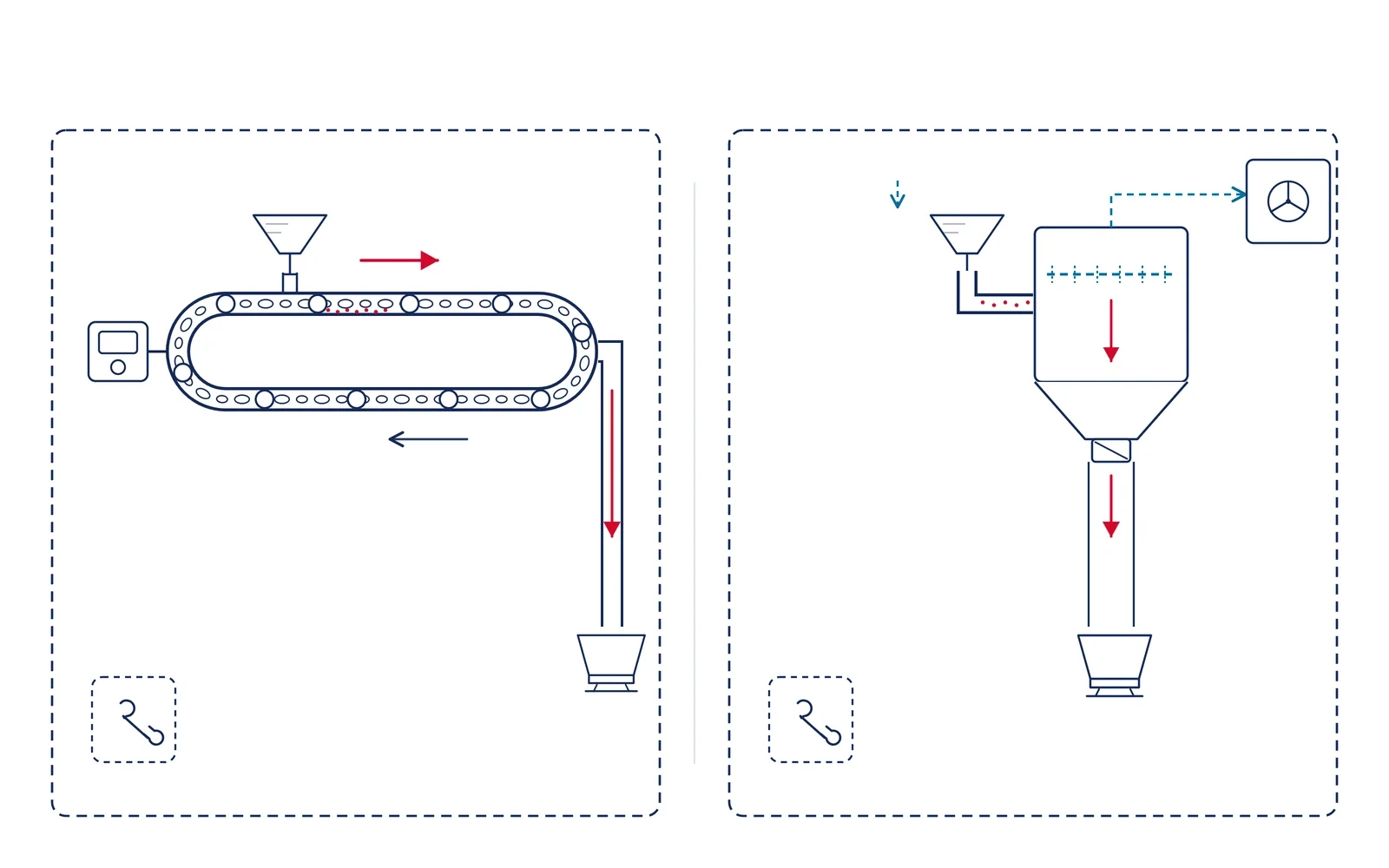
State whether the next machine requires steady feeding or can accept intermittent delivery. Include the batch size and allowed transfer window. A supplier should explain how the proposed conveyor, receiver and any buffer hopper will satisfy that demand together. An average hourly capacity alone may conceal an unacceptable interruption during a production cycle.
Containment and cleaning are separate questions
Enclosure is a useful starting point, but it is not evidence of zero dust escape or zero cross-contamination. Ask how the complete installation handles connections, access covers, receiver discharge and cleaning. Set an acceptance method appropriate to the material and workplace rather than relying on a general marketing description.
For changeovers, specify the previous product, the next product and the acceptable carryover. Ask who opens the system, which parts are removed, what tools are needed, how cleaning is checked and how long the complete procedure takes. If wet cleaning is proposed, confirm drainage, drying and compatibility with the actual material before accepting it.
Combustible powders require a separate safety review: enclosure by itself does not establish explosion safety. Qualified personnel should evaluate the specific material and installation. OSHA’s combustible dust overview provides general hazard context, not approval of a particular conveyor.
How to Compare Energy, Maintenance and Total Cost
Do not compare one motor nameplate with a complete installed system. Ask each supplier to define the measurement boundary and operating assumptions. Include auxiliaries, idle periods and start-stop behavior relevant to your production schedule. A credible comparison explains what was measured, calculated or merely estimated.
Use energy per delivered tonne = total measured system energy divided by delivered mass. Compare results at the same material condition, route and useful output. This is an evaluation method, not a claim that either conveyor achieves a particular consumption. Report electrical energy in kWh per delivered tonne. Include measured or consistently allocated compressor energy where compressed air is used, without double-counting. Compare utility cost per tonne separately, using the same tariff and allocation assumptions.
Build a maintenance comparison around planned tasks and likely downtime. Ask for wear-part identifiers, replacement access, local availability and recommended inspection intervals for the proposed duty. Obtain the assumptions behind any quoted annual maintenance cost. Add cleaning labor, rejected product and changeover losses where they affect your process.
A Practical Shortlisting and Trial Workflow
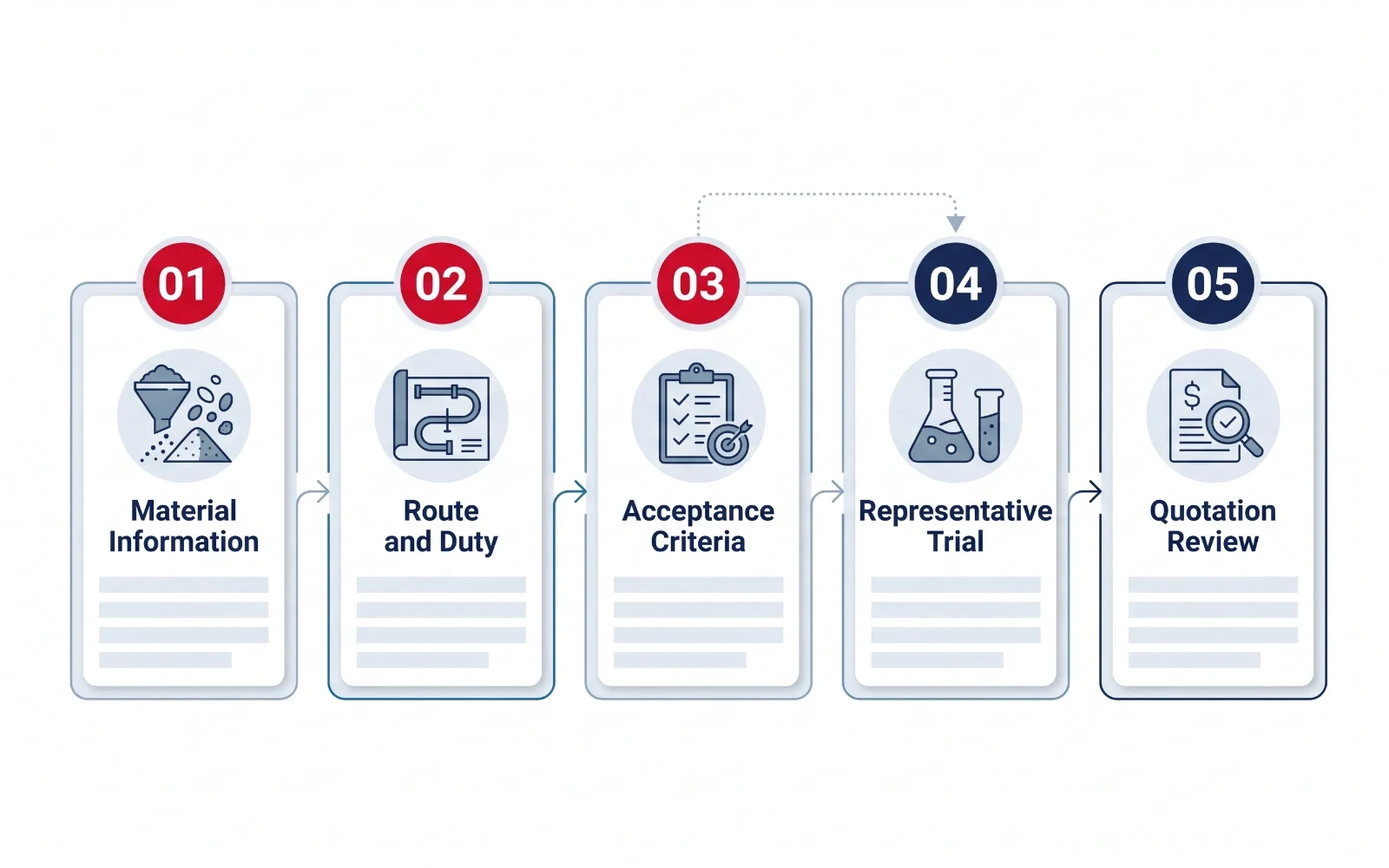
- Write the duty statement. Define material, normal and peak output, batch size, operating hours and the required receiving condition.
- Set pass/fail criteria. Agree acceptable damage, residue, delivery variation and any cleanliness requirements before the test.
- Issue the same layout and sample information. Require both proposals to identify exclusions and utility requirements.
- Request a representative trial. Record the sample condition, route used and differences from the final installation. Do not extrapolate unexplained test results to a more demanding duty.
- Review the complete quotation. Compare installed scope, controls, access, service support and acceptance responsibilities.
For a tubular chain proposal, verify space for the loaded circuit, return path, drive and service access, together with acceptable wear, breakage and residue in a representative assessment. For a vacuum proposal, verify pickup, gas-solid separation, filtration and discharge timing against downstream demand, available utilities and permitted gas contact. These questions help build a shortlist; they do not establish suitability without application review. Explore UNITFINE’s conveying equipment range if another arrangement also deserves consideration.
Frequently Asked Questions
Is a vacuum conveyor a pneumatic conveyor?
Yes. Vacuum conveying is a pneumatic arrangement that draws material toward a receiver using a pressure difference. The conveying phase and whether delivery is cyclic or continuous must be specified separately.
Is a tubular chain conveyor always gentler?
No. Product damage depends on the material and the complete transfer arrangement. Compare both proposed systems in a representative trial using agreed measurements of breakage, fines or blend consistency.
Which conveyor uses less energy?
There is no universal answer. Compare complete-system energy per delivered tonne for the same material, route and duty, including gas generation, drives and relevant auxiliaries.
Can either system guarantee dust-free transfer?
Not from the technology name alone. Containment depends on connections, seals, operation, maintenance and the receiving process. Agree an appropriate assessment method for the installed system.
Are tubular chain and tubular cable conveyors the same?
No. Both are enclosed mechanical drag arrangements, but one uses a chain and the other a cable. Their components, maintenance requirements and approved applications must be assessed separately.
What information should I send for a quotation?
For an initial review, send the material description and sample information, bulk density, particle-size range, moisture, normal and peak output, batch schedule, route drawing, utility availability, cleaning needs and product-quality acceptance criteria. As applicable, also provide material and ambient temperature, abrasiveness or adhesion, permitted gas contact and known hazard information. Additional design inputs may be required.
Ask UNITFINE to Compare Your Conveying Duty
Send your material information, required output, route drawing and acceptance criteria. Ask for a comparison of the tubular chain and vacuum-conveying options, with testing needs, scope exclusions and utility assumptions clearly identified.
Technical References and Scope
This guide provides a purchasing comparison framework, not a certified equipment specification. Working-principle references include UNITFINE’s linked product pages, Piab’s pneumatic conveying explanation and Hapman’s tubular drag conveyor description. Manufacturer-specific ratings and options must not be transferred to a UNITFINE quotation. No supplier’s general marketing statement substitutes for application testing.